Hard Grey Scale (HGS), a costly fouling phenomenon in the aluminium production industry.
Fouling is the accumulation of unwanted material on solid surfaces. It comes in many forms: corrosion, particulate fouling (dust), precipitation fouling (scaling) or biofouling, among others.
The formation of such deposit layers affects the performance of equipment, for example filters or heat exchanging surfaces, and causes clogging issues that require costly periodic maintenance. The economic impact of fouling only in heat exchangers was estimated to be in the range of 0.25% of the GDP in industrialized countries [1].
In the aluminium production industry, a type of fouling commonly known as “Hard grey scale” (HGS) is produced in systems in contact with the off-gas generated in the electrolysis cells where aluminium is produced. The off-gas is a mixture of reactive particulates and corrosive gases that needs to be cleaned in the Gas Treatment Center (GTC) before it is safely released to the atmosphere. The growth of HGS causes problems in the system responsible for the absorption of the hazardous hydrogen fluoride (HF) and the pipes transporting alumina (used to absorb HF) to the electrolysis cells as can be seen in the figure below. Therefore, the growth of HGS can have detrimental effects in both emissions and process control.
Quite surprisingly, there were very few studies dealing directly with HGS formation at the beginning of the project and there was much uncertainty regarding the growth rates and mechanisms.

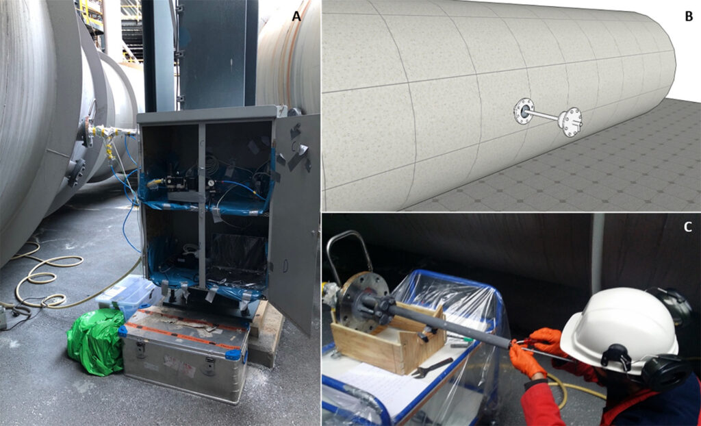
To study HGS formation systematically, we designed and built a cooled fouling probe, commonly known as “cold-finger”
The cold-finger was designed to enable us to replace the outer tube where HGS was forming after each experiment. This allowed having reproducible initial surface conditions and to cut the tubes with deposits to analyze the cross-sections. In addition, multiple sensors were placed in the surface of an inner tube, which we use to monitor the effect of HGS growth on heat transfer by circulating pressurized air as coolant.
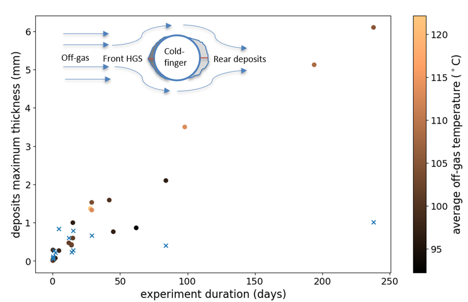
More than 30 cold-finger experiments were conducted over the course of nearly three years with durations ranging from a few hours up to eight months. As can be seen in the figure below, the results clearly showed that the growth of HGS (circles) was linear with time with an average growth rate of 0.9 mm/month. That means that no signs of growth stabilization were observed, as opposed to a different type of dusty and loosely attached deposits (crosses) forming on the rear side of the probe. This constant growth is why HGS is able, given time, to choke whole pipes and be highly problematic.
HGS was named after a type of precipitation fouling (scaling) whereas in fact it is a type of particulate fouling.
The term “scale” refers to precipitation processes where a supersaturated solute crystallizes on a surface, which produces deposits with similar characteristics as HGS. However, by means of electron microscopy we soon realized that HGS was composed of very small individual particles forming a closely packed structure which pointed out to a type of particulate fouling instead.
We then used an image analysis program developed within the department [3] in order to study the particle size distribution of the deposits and off-gas particles. This in turn was used to calculate the particle deposition characteristics, which could be compared with computational fluid dynamic simulations. As can be seen in the figures below, HGS is produced from the smallest particle fraction in the off-gas, resulting in a very compact structure that can explain the bulk hardness of the material.
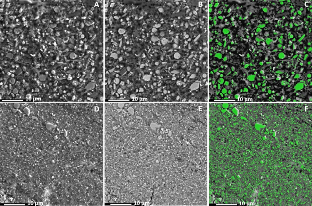
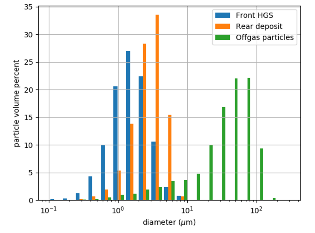
The key ingredient in the formation of HGS was found to be the nano-particles produced during the quenching of the electrolyte vapors in the form of atmolite (NaAlF4)
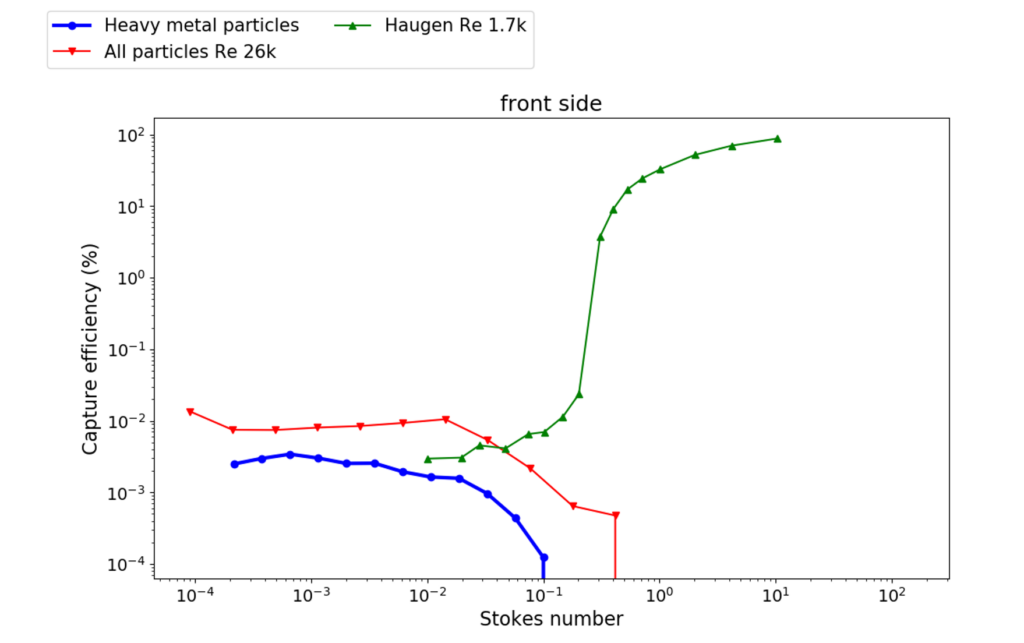
As particles become small enough (i.e. Stokes numbers below 0.1) their inertia becomes insignificant and thus they follow the fluid streamlines that carries them almost perfectly. For Stokes numbers above 0.1 particles start to become more and more inertial which increases their impaction efficiency by many orders of magnitude as they approach a cylinder as can be seen in the CFD simulations by Haugen et al [4]. The small diffusional particles that perfectly follow the fluid streamlines can still impact the surface of a cylinder due to their finite size in what is called “interception mechanism”. This mechanism agrees very well with the cold-finger experiments and it is even consistent with the lower capture efficiency rates of a heavy metal rich type of particles which could be identified separately using image analysis due to their different contrast in SEM images. Finally, quantitative XRD analysis also confirmed the crucial role of the atmolite nano-particles not only in the cold-finger HGS, but also in a different type of HGS from an alumina transport pipe, collected in a previous project.
Reducing the quenching effect might be a way of mitigating and even avoiding HGS formation.
Nowadays, the vapors emanating from the electrolyte during aluminium production are diluted 1000 times by air suction from the pot room, which causes the formation of nano-particles due to the strong quenching effect. Strategies such as reducing the volume of air suction or off-gas recirculation with eventual preheating before mixture with the cell vapors, would aid reducing the formation of nano-particles and might eventually avoid HGS formation. Such strategies have been investigated in recent years in order to both reduce fans power consumption and to increase the concentration of CO2 in the off-gas to levels where it can be economically feasible to apply carbon capture methods. These strategies also increase the potential for heat recovery due to increase in off-gas temperatures.
References
[1] H. Mueller-Steinhagen and A. P. Watkinson, “Fouling of Heat Exchanger-New Approaches to Solve an Old Problem,” Heat Transf. Eng., vol. 26, no. 2, 2005.
[2] N. R. Dando and S. J. Lindsay, “Hard Grey Scale,” in Light Metals, 2008, pp. 227–232.
[3] H. Zedel, R. Fritzsch, S. Akhtar, and R. Aune, “Estimation of Aluminum Melt Filtration Efficiency Using Automated Image Acquisition and Processing,” in Light Metals, 2019, pp. 1113–1120.
[4] N. E. L. Haugen and S. Kragset, “Particle Impaction on a Cylinder in a Crossflow as Function of Stokes and Reynolds Numbers,” J. Fluid Mech., vol. 661, pp. 239–261, 2010.

